Understanding Lithium Polymer Cells and Basic Chemistry
Lithium polymer batteries deliver impressive power-to-weight ratios for radio-controlled models, drones, and tactical gear, but their volatile chemical makeup demands disciplined charging habits. Unlike older nickel-metal hydride cells that tolerate minor overcharging, a single lithium polymer cell operates within a strict voltage window between 3.0 volts fully depleted and 4.20 volts fully charged. Exceeding those physical boundaries causes internal decomposition, gas generation, and potential thermal runaway.
Every multi-cell pack consists of individual foil pouches wired in series to build working voltage. A nominal cell rating rests around 3.7 volts, meaning a two-cell configuration delivers 7.4 volts nominal while a three-cell assembly produces 11.1 volts nominal. Because individual pouch capacities and internal resistances drift apart over repeated discharge cycles, balancing each cell during every charge routine remains essential to long-term reliability and personal safety.
Charging these packs requires constant-current followed by constant-voltage cycles rather than a continuous wall-trickle stream. When you connect a pack, the electronics feed steady amperage until individual cells hit their maximum threshold, at which point current tapers down gradually while leveling voltages across the entire series. Neglecting this balancing process invites an uneven load where one cell overcharges silently while the overall pack appears normal.
Setting and Maintaining Correct LiPo Storage Voltage
Leaving lithium polymer packs fully charged on a shelf is one of the quickest ways to ruin their internal chemistry and induce permanent capacity loss. Chemical stability inside the cell peaks between 3.80 and 3.85 volts per cell, which serves as the universal industry benchmark for long-term storage. Storing packs at 4.20 volts puts immense stress on the cathode materials, leading to internal resistance spikes, capacity fade, and physical puffing within several days.

Conversely, allowing packs to sit below 3.50 volts per cell risks parasitic self-discharge dropping the chemistry below its irreversible copper-dissolution threshold. When cell voltage dips under roughly 2.8 volts, copper shunts form inside the pouch, turning subsequent recharge attempts into serious fire hazards. Using your unit's automated storage routine balances each internal cell to roughly 3.82 volts whether the pack began the afternoon completely depleted or completely full.
If you run remote-controlled rigs or test electronic markers across venues listed on paintballatlas.com, develop a habit of cycling all packs into storage mode within twenty-four hours of field return. Modern computerized units allow you to select a dedicated storage cycle that automatically calculates whether current needs to be added or safely discharged through internal heat sinks to reach target resting thresholds.
Managing Low Cell Counts and Charging 1S Packs
Single-cell packs, commonly designated as 1S batteries, run at 3.7 volts nominal and require specialized attention because they lack a separate balance connector. Because only two power leads exit the pack, the charger reads and regulates the entire assembly through the main discharge plug alone. Charging small 1S packs used in ultra-micro vehicles or compact gear requires close verification of charging rate to avoid pushing excessive current into tiny internal plates.
The standard charging standard for nearly all lithium polymer chemistries is 1C, meaning the charge current equals the total capacity divided by one hour. For example, a small 300 milliamp-hour 1S pack should typically be charged at 0.3 amps, while a larger 800 milliamp-hour unit should see no more than 0.8 amps unless explicitly rated for faster charging by the manufacturer. Pushing multi-amp rates into compact cells generates rapid heat buildup that damages cell separators.
Multi-board splitters allow enthusiasts to hook up several 1S batteries at once, but series charging and parallel charging require completely different configurations. Parallel boards demand that every connected battery sits within roughly 0.1 volts of each other before connection to prevent sudden current surges between packs, whereas dedicated multi-channel docks treat each 1S battery as an independent, isolated circuit with dedicated current control.
Configuring Dedicated Two-Cell Balance Rigs
A 2S charger setup manages 7.4-volt systems found across recreational buggies, stadium trucks, and receivers, relying on both main leads and a three-pin balance connector. The primary leads handle high-amperage delivery while the balance harness monitors individual cell potentials to millimeter-volt accuracy throughout the cycle. Attempting to charge any 2S pack without plugging in its balance lead bypasses critical over-voltage safeguards.
When configuring your station for two-cell operation, verify that the display recognizes both individual cell voltages before initiating the charge cycle. A healthy discharged 2S battery usually shows both cells hovering somewhere between 3.60 and 3.75 volts at rest. If the display reveals a discrepancy greater than 0.15 volts between cell one and cell two prior to charging, that pack requires a gentle low-amperage balance pass to see if equilibrium restores naturally.
Compact sport chargers often handle 2S packs through automated plug-and-play interfaces that detect cell count through the balance connector alone. While convenient for beginners, advanced microprocessor units allow manual adjustment of charge rates and termination voltage, giving users greater control over cell longevity. Ensuring tight balance on your two-cell packs prevents thermal stress during intense weekend runs.
High Capacity Batteries and Three-Cell Pack Demands
Stepping up to heavier remote-controlled vehicles often involves running robust assemblies like a Traxxas LiPo 3S 5000mAh pack capable of delivering intense bursts of speed and torque. At 11.1 volts nominal and 12.6 volts peak, a three-cell 5000mAh unit contains substantial potential energy that requires an equally capable power supply. Charging a pack of this capacity at a baseline 1C rate requires a continuous output of 5.0 amps at roughly 63 watts.
Many entry-level power supplies cap output around 50 watts, which throttles the charge current as voltage climbs toward the 12.6-volt ceiling. If your charging unit cannot supply sufficient wattage, the cycle prolongs substantially, causing charging circuits to run hot. Selecting a station with an output rating of 80 to 100 watts provides comfortable headroom for 3S packs without pushing the power brick to its absolute thermal limit.
Large three-cell blocks also generate noticeable internal heat when charged back-to-back following aggressive operation. Always allow a 3S pack to cool down to ambient room temperature before initiating a fresh charge routine. Connecting a warm or hot pack directly from your vehicle accelerates chemical aging and can trigger false peak readings on automated balancing circuits.
Navigating Proprietary Battery Connectors and Ecosystems
Manufacturers occasionally develop proprietary connector formats to simplify operations for hobbyists, as seen when charging a Traxxas battery equipped with automated ID chips. These proprietary connectors integrate the balance wires directly into the primary plug housing, allowing compatible chargers to read cell health without requiring a separate balance lead dangling from the battery casing. The unit recognizes the battery model immediately and configures appropriate current parameters automatically.

Working with a dedicated battery Traxxas charger keeps the process straightforward for newcomers, but experienced operators often prefer universal balance chargers to manage diverse gear fleets. Adapters are widely available to bridge proprietary multi-pin connectors with standard balance boards and banana leads. When using conversion leads, take care to route balancing pins accurately, as an inverted balance lead connection can trigger short circuits across the adapter board.
Whether you stick with unified plug systems or solder generic balance connections like XT60 or Deans plugs, maintaining clean gold-plated contact surfaces is critical. Arcing, oxidation, or dirt within the terminals raises resistance, which misleads the charger into thinking a cell has reached full voltage prematurely. Inspect all plug housings regularly for melted plastic, loose pins, or frayed wire strain reliefs.
Understanding High Voltage Chemistry and LiHV Settings
High-voltage lithium polymer cells, abbreviated as LiHV, feature modified electrolyte chemistry that safely supports charging up to 4.35 volts per cell rather than the traditional 4.20-volt ceiling. This extra 0.15 volts per cell delivers higher initial RPM, flatter discharge curves, and extended runtimes in competitive applications. However, maximizing this chemistry requires using a compatible LiHV charger equipped with an explicit high-voltage firmware profile.
Under no circumstances should you ever charge standard lithium polymer packs using a high-voltage profile. Forcing 4.35 volts into a standard 4.20-volt cell over-saturates the cathode, breaks down organic solvents within the electrolyte, and generates volatile gas within minutes. This mistake remains one of the primary causes of workshop fires among hobbyists who inadvertently leave their stations locked on high-voltage mode.
Conversely, charging a genuine high-voltage pack on a standard lithium profile is completely safe, although it yields slightly lower maximum capacity. Many endurance racers intentionally charge their high-voltage cells to standard 4.20-volt levels to extend the total calendar life of the pack from dozens of cycles to hundreds of cycles, sacrificing a small margin of initial speed for long-term economy.
Operating Microprocessor and Multifunction Stations
Multi-chemistry programmable workstations, such as the venerable IMAX B6 charger platform and versatile Ovonic battery charger units, remain workshop mainstays due to their wide compatibility. These stations support standard lithium, high-voltage chemistry, lithium iron phosphate, and legacy nickel packs through a shared menu system. Understanding the multi-button navigation allows users to tailor charge currents, cell cutoffs, and balancing speeds with high precision.
Setting up a balance cycle on a programmable microprocessor unit requires confirming two critical numbers: total series cell count and charging current. The display typically prompts for cell count confirmation before initiating current delivery, requiring the operator to match the on-screen reading with physical battery labels. Never press through confirmation prompts without visually cross-referencing cell counts against the real pack.
Quality programmable stations also feature internal resistance measurement menus that reveal individual cell health across milliohm scales. Fresh, healthy performance packs typically show internal resistance figures under 5 milliohms per cell, while heavily worn or degraded cells frequently climb past 15 to 20 milliohms. Monitoring internal resistance over time provides clear warning signals before a deteriorating cell causes voltage sag or sudden failure.
If you encounter connection errors or voltage mismatch warnings, double check your balance adapter board and power brick cables before suspecting internal component failure. Many false errors stem from worn balance ribbon cables rather than damaged internal components.
Physical Battery Safety, Fire Containment, and Daily Handling
Rigorous adherence to LiPo safety protocols forms the foundation of responsible battery ownership across remote-controlled vehicles and field operations. Because lithium polymer pouches rely on flexible laminate casings rather than rigid steel canisters, physical puncture, crushing, or excessive vibration can easily cause internal short circuits. When an internal separator fails, stored chemical energy converts directly into intense heat, reaching temperatures that ignite nearby flammables.
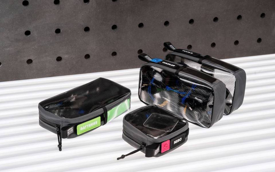
Always charge your packs inside a fire-resistant container such as an authentic fiberglass charging sack, heavy steel ammo box, or ceramic charging bunker. Position this charging container on a concrete or tile floor well away from curtains, cardboard boxes, and flammable chemicals. Never leave an active charging station completely unattended; being present in the room or adjacent workshop allows you to disconnect power at the first sign of smoke or unusual odor.
For enthusiasts traveling to venues like Paintball Fields That Also Offer Airsoft or practicing inside Indoor Paintball Fields across Texas, pack transport requires dedicated care. Secure all batteries in rigid, padded cases to prevent sharp tools or loose hardware from puncturing cell walls during transit. Keep terminal caps installed on all discharge leads to eliminate the possibility of accidental metal-to-metal contact inside your gear bag.
Recognizing Degradation, Swelling, and Proper Disposal
Even with meticulous charging habits, every lithium polymer pack eventually reaches the end of its useful service life. Physical swelling—often described as puffing—occurs when decomposing electrolyte produces gaseous hydrocarbons that expand the sealed outer pouch. While minor soft swelling after aggressive, hot runs can occasionally subside, persistent firm swelling indicates broken internal separators and compromised integrity that warrants immediate retirement.
Continuing to cycle a swollen battery significantly elevates fire risk, as expanding foil layers exert uneven mechanical pressure on internal electrode coatings. If you notice a pack becoming warm during a storage cycle or balance routine, disconnect the power source immediately and relocate the pack to an isolated outdoor fireproof area. Monitor the battery for several hours until chemical activity stabilizes and temperatures cool completely.
Safe disposal begins with completely depleting the remaining charge to zero volts so no reactive energy remains. Connect the spent pack to a small automotive light bulb or dedicated resistive discharger until voltage reads absolute zero across all cells. Once fully discharged, check municipal guidelines or regional battery drop-off locations; in most states, local recycling centers handle fully depleted lithium cells safely without requiring old-fashioned, corrosive salt-water soak methods.
Published 2026-09-21 · reviewed with each rebuild, last October 2026.
Find paintball fields & fun centers near you
The directory lists 36,923 paintball fields & fun centers by state and city — pick your state or use the “Near me” button in the header.
More guides
-
 Service
Where and How to Refill Paintball CO2 and HPA Tanks
-
 Buying
A Guide to Purchasing Your Own Paintball Equipment
-
 Safety
Paintball vs Airsoft: Evaluating Impact, Costs, and Removing Stubborn Stains
-
 Money
MoneyHow Much Does Paintball Cost? Field Fees, Rental Packages, and Ammo Math
-
 Safety
Does Paintball Hurt? Safety, Bruises, Clothing, and Stains
-
 Buying
Where to Sell Used Paintball Guns Safely and Clean Up Gear
-
 Safety
Beginner's Guide to Paintball: Understanding Game Formats and Rules
-
 Money
MoneyPaintball Cost Guide: Equipment, Field Fees, and Play Prices
-
 Owning
How to Remove Paint and Acrylic Stains from Clothing and Fabrics
-
 Buying
Tactical and Military Boots: Brands, Comfort, and Field Selection
-
 Service
Corporate Team Building and Outdoor Adventure Events: The Complete Organizer's Guide
-
 Buying
Laser Tag Arenas, Equipment, and Home Party Rentals Guide
-
 Safety
LiPo Battery Maintenance, Safe Charging, and Balance Chargers for Gear
-
 Service
Indoor and Outdoor Paintball Fields: Venue Selection, Booking, and Rules
-
 Buying
Complete Paintball Equipment Guide: Markers, Air Tanks, Jerseys, and Field Attire
-
 Safety
Whitewater Rafting and River Adventure Parks: Destinations, Trips, and Safety Guide
-
 Safety
Airsoft Fields and Arenas Guide: Indoor vs Outdoor Venues, Rules, and Rentals
-
 Buying
Laser Tag Centers, Home Equipment, and Event Planning Complete Guide
-
 Service
Paintball Fields, Scenario Games, Night Ops, and Arena Booking Guide
-
 Safety
Ziplining and Aerial Trekking Parks: Top Courses, Safety Standards, and Booking
-
 Buying
Tactical Combat Boots Buying Guide: Military Specs, Fit, and Durability
-
 Owning
Paintball Marker Maintenance, Air Systems, and Tank Safety Guide
-
 Safety
What to Wear for Paintball: Clothing, Protective Gear, and Cleaning Paint Stains
-
 Owning
Airsoft Gear and Milsim Accessories: Speedloaders, Tracers, and Camouflage
-
 Safety
Paintball Age Limits, Tactics, and Corporate Event Planning
-
 Owning
Paintball Video Games, Consoles, and Digital Arenas: An Off-Field Player Guide
-
 Service
CO2 Tank Refills and Compressed Air Systems: Options, Locations, and Safety Rules
-
 Owning
Archery Games Guide: Online Simulators to Adult Field Events
-
 Buying
Complete Airsoft Guns and Equipment Guide: Reviews, Rentals, and Legal Safety
-
 Owning
Paintball Gear & Maintenance Guide: Custom Apparel, Tank Fills, and Stain Removal
-
 Service
Ultimate Guide to Indoor Soccer Zones: Leagues, Facilities, and Play Options